Energy efficiency is one of the most important aspects of green building design. The following are some basic terms that one needs to comprehend before going any further in understanding “Building Insulation” or assessing “Thermal Insulation” of a building.
k VALUE /κ VALUE = THERMAL CONDUCTIVITY is the amount of heat that will go across a meter thickness of a square meter of material if the temperature difference between the two ends is 10Celsius (W/m2 0C). It is a material-specific property at a specified temperature. This property characterizes the thermal insulation property of the building materials.
U VALUE= THERMAL CONDUCTIVITY, but for an assembly of various materials in series. It defines the Thermal conductivity of a roof or wall assembly and indicates how easily heat can enter or exit the building.
R-VALUE = THERMAL RESISTANCE of a Building wall or Roof assembly. It is inverse of U or 1/U = R1+R2+…+Rn =1/ λ1+ 1/λ2+…+1/λn. It is just the reverse of the U value. It characterizes how the wall or roof assembly of a building resists the influx of Heat or Cold.
µ VALUE = WATER VAPOUR RESISTANCE FACTOR is a property of the building material indicating its resistance to the passage of moisture through the layer when compared to resistance to flow of moisture in an equivalently thick layer of air.
µ.d is a product of µ with the material thickness that indicates the equivalent air gap in terms of moisture movement.
Degree Days = Product of the temperature Difference (Avg) during a day between ambient and inside temperature. These values can be downloaded for most Indian stations from http://www.degreedays.net. These can then be totaled to get the degree days for a year.
Dew Point = The temperature at which moisture in ambient air saturates and starts condensing out of the air. It is an important parameter in HVAC / insulation design.
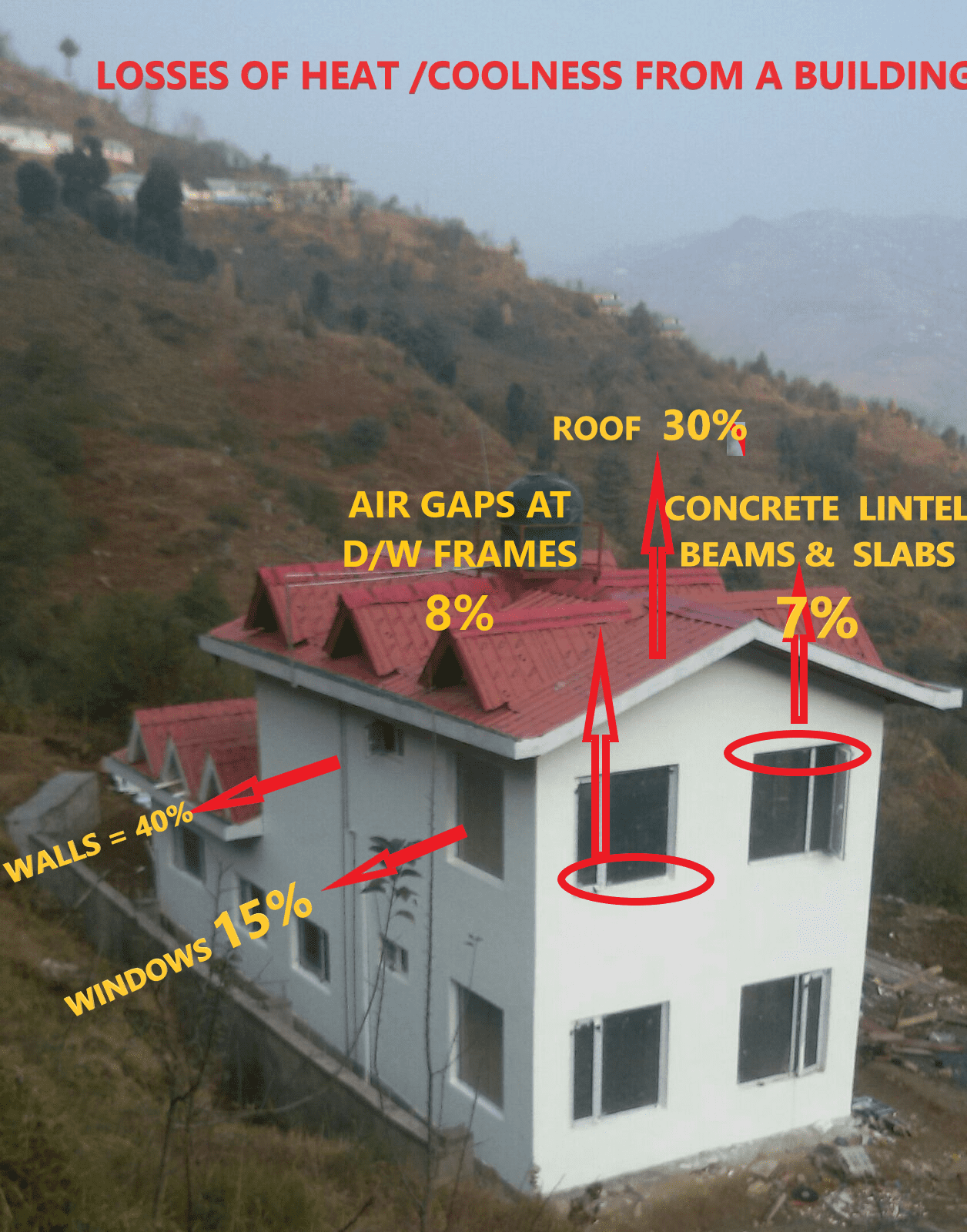
Four ways of losing Heating or Cooling energy

We can create a moat to protect our green building against these four routes of heat influx. This will complete the thermal engineering aspect of the green building design. This method is called the Red Line method in Green Building design parlance. The lesser energy that this moat creation takes from cradle to grave, the lesser harm it causes to the environment and the greener the building is.

Red Line Method showing the moat which would need to stop the four routes of heat flux.
Thermal Bridging a major source of Heat / Cooling Loss

An important aspect to be taken care of is Thermal Bridging. These are areas of significantly higher thermal conductivity (k value) within the insulation layer. In this thermographic image, you can see a higher temperature image of the slab beam. Concrete with steel can be a major source of heat ingress into your air-conditioned interiors. The image on the right side is of a roof with insulation sheets laid. It shows the joining edges of sheets lit up in orange, indicating the thermal bridging of the sheet joints.
At the design stage, one can take care of Thermal bridges. For flat roofs, use molded interlocking insulation tiles like Reliable Kooltiles or apply a staggered double layer of insulation.
In walls, use EIFS or Exterior Insulation & Finishing System to avoid thermal bridging.

Note that we are treating convection and air infiltration separately as different means of heat gain or loss. Convection currents can be there even without air infiltration. In an improperly insulated room, with significant thermal bridging, air draft is felt because of the circulation of cold air.
Firstly the moat (insulation+ design) has to be taken care of in a sustainable fashion. Then the thermal bridges are avoided through design intelligence. Now we have a green building design ready that is satisfactory and sustainable. To assess energy-saving through insulation or total HVAC load that the building envelope will contribute to, we would need to calculate the U factor of the wall and roof assemblies. For this, you may use the “U Value Calculator” designed by Reliable Building Solutions, which shall appear as under:
How to use the U Value calculator

This U value calculator does automatic calculations after you feed in the parameters into the green-colored cells. The choice of layers in the roof or wall assembly is made in the orange cells by choosing from the dropdown of the cell. The calculation results are provided in the yellow cells. On the last column on the right, if a cell gets highlighted in pink, one can infer that dew condensation is likely to happen in those layers and some redesigning is required to avoid the same. For more information about building insulation, and Reliable Building Solution’s thermal insulation products and service, please visit https://www.reliableinsupacks.com
Pingback: Overdeck insulation on metal roofs, insulates hailstorm sounds also — Greener, Safer, Stronger, Faster Construction
Pingback: the importance of building insulation in habitat design — Greener, Safer, Stronger, Faster Construction
Pingback: Thermal Insulation layer in Building Envelope can Solve Moisture Condensation issues in building Interiors ⋆ Greengineers Construction Blogs